Come demo the Sidekick at our new location at the Burlington Mall, Burlington, MA.
Email hello@dephy.com to schedule an in-person demo or check @movewithdephy on Instagram or Facebook to see our daily demo hours.
Movement, Your Way.
Enjoy every step with the Sidekick.
Shop NowEnjoy every step with the Sidekick.
Shop Now
The things you love to do shouldn't feel out of reach.
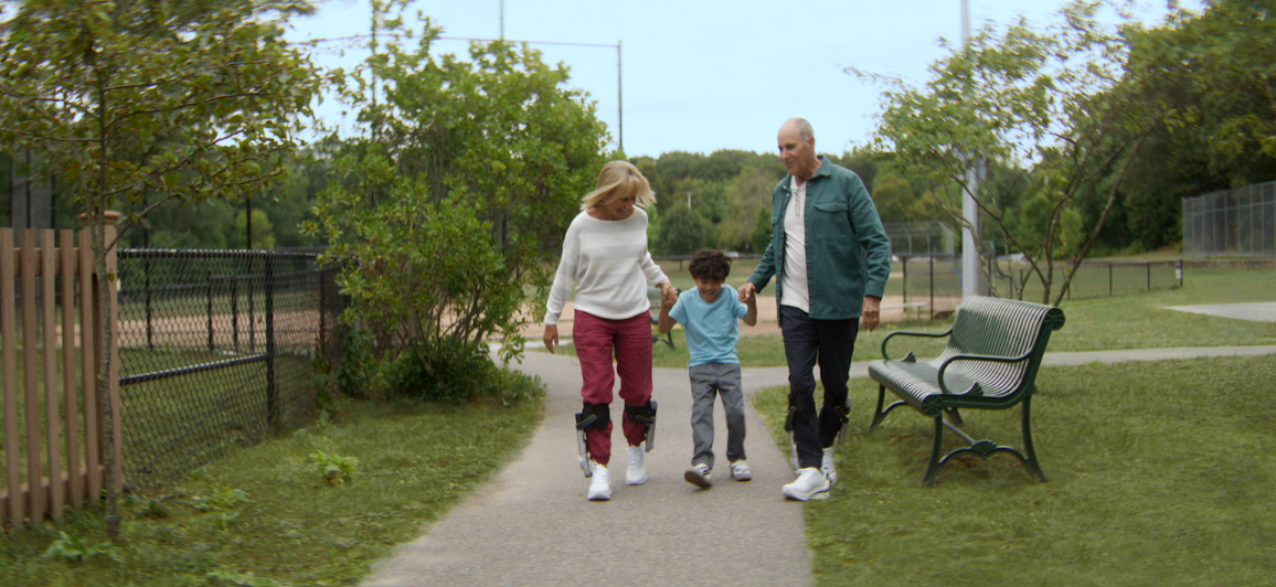
Walking used to feel like a given. Now it takes more out of you than it should. More planning, more recovery, more effort just to get through the day. The Sidekick helps with exactly that.
The Sidekick is a powered footwear system that gives you a gentle boost with every step, reducing the effort your body has to do on its own, so walking feels easier, more comfortable, and more like you. It doesn't walk for you but rather with your stride. You stay in control and the Sidekick adds support exactly when it matters most.
The Sidekick system is not a medical device. It's a wellness product built for people who want to move through their day with less effort and more confidence, whether that's a walk around the block or a day on your feet.
%20Stk(%23fff)%20Cur(p)'%20width='152'%20style='stroke-width:0;vertical-align:bottom'%20height='33'%20viewBox='0%200%20152%2033'%3e%3cpath%20d='M0%2024.1C0%2025.7%201.3%2027%203%2027h12v-3H3v-3h11.8c1.6%200%203.2-1.3%203.2-2.9v.1-5.9c0-1.6-1.5-3.2-3.2-3.2H3c-1.6%200-3%201.6-3%203.2v11.8zM15%2018H3v-6h12v6zm40.1-9H43.2c-1.6%200-3.2%201.6-3.2%203.2v11.9-.1c0%201.6%201.6%203%203.2%203H55v3H43v3h12.1c1.6%200%202.9-1.4%202.9-3V12.2c0-1.6-1.3-3.2-2.9-3.2zM55%2024H43V12h12v12zM32%209h-8.9c-1.6%200-3.1%201.6-3.1%203.2V27h3V12h9c1.6%200%203%201.5%203%203.2V27h3V15.2c0-3.3-2.7-6.2-6-6.2zm43%2015H63v-8.9c0-1.6%201.6-3.2%203.3-3.2H75v15h3V12.2c0-1.6-1.2-3.2-2.8-3.2h-8.9C63%209%2060%2011.9%2060%2015.2v8.9c0%201.6%201.7%202.9%203.3%202.9h5.2c2.7%200%205.5-1.1%206.5-3v3m68-27h-3v27h3V12h9V9h-9zm-42%2024.1c0%201.6.9%202.9%202.5%202.9H115v3h-11v3h11.4c1.6%200%202.6-1.4%202.6-3.1v.1-17.8c0-1.6-1-3.2-2.6-3.2h-11.9c-1.6%200-2.5%201.6-2.5%203.2v11.9zm14-.1h-11V12h11v12zM95%209H83.4c-1.6%200-3.4%201.6-3.4%203.2v11.9-.1c0%201.6%201.8%203%203.4%203H98V0h-3v9zm0%2015H83V12h12v12zm25%20.1c0%201.6%201.7%202.9%203.3%202.9H135v-3h-12v-3h12.2c1.6%200%202.8-1.3%202.8-2.9v.1-5.9c0-1.6-1.2-3.2-2.8-3.2h-11.9c-1.6%200-3.3%201.6-3.3%203.2v11.8zm15-6.1h-12v-6h12v6z'%20stroke='%23FFFFFF'%20fill='%23000000'%20stroke-width='0px'%3e%3c/path%3e%3c/svg%3e)


Walk farther.
Do more.
REAL STORIES · REAL VOICES
We think about movement a lot at Dephy. Not the extreme kind, the everyday kind. A full day on your feet. Keeping up with the people you love. Exploring somewhere new without wondering how far you can go.
Maybe you have joint stiffness or leg discomfort that's slowed your pace. Maybe you feel more fatigued during your normal routine than you used to or maybe your body just needs more support to get through the day. Either way, you haven't stopped wanting to move.
Hear from people who are experiencing life with the Sidekick.
Get back to what you love
I feel like I can do anything. They've given me hope, joy, and a level of mobility I didn't think I'd get back.
— Tamara G., 46
Ready in minutes. Built for every day.
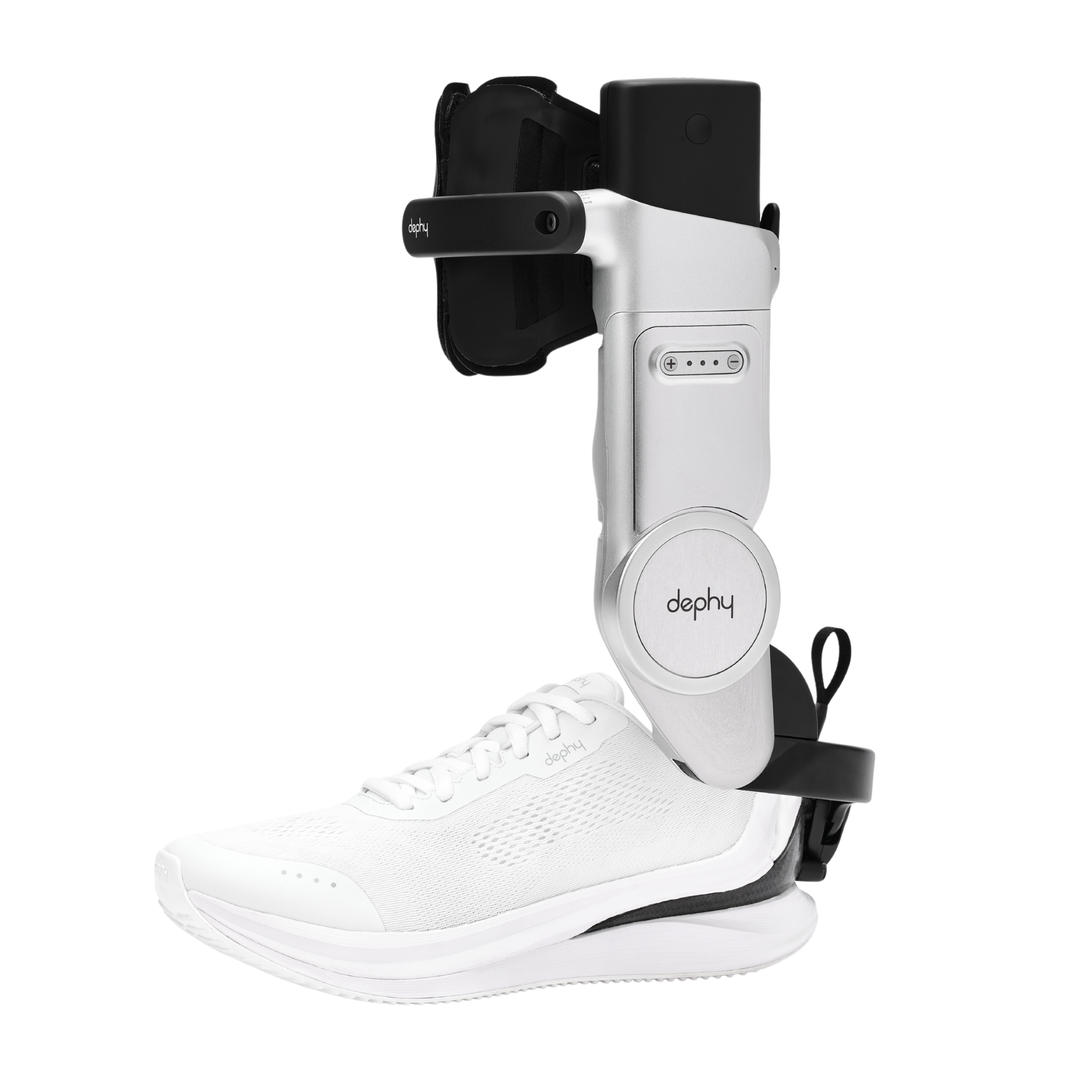
Lace Up
Put on your Sidekick-compatible shoes and attach the Sidekick to each leg.
Power On
Insert the charged batteries, power on and get ready to train your Sidekicks
Walk
Within 20 strides, the Sidekick learns how you walk, supporting your movement and makes every step feel lighter and easier.
WHY THE ANKLE
Why the ankle, and not somewhere else?
Most exoskeletons target the hip or the knee. That's where you feel discomfort, but it's not where walking effort originates. The ankle generates up to 60% of the energy needed to walk. Targeting it directly means less effort at the source, and less strain on every joint above it.
Learn How the Sidekick WorksFind out if the Sidekick is your next step.
If you want to move more comfortably, go farther, and stop working around what your body will and won't do, you're probably exactly who we built this for.
Take your next step. Shop the Sidekick.
Get yours today and start moving with more ease, comfort, and confidence.
Shop NowFind out if the Sidekick is right for you in 60 seconds.